- CH
-
Current location :Home > Production Center > Optical Smart Water Meter > Camera Non-magnetic Smart Water Meter
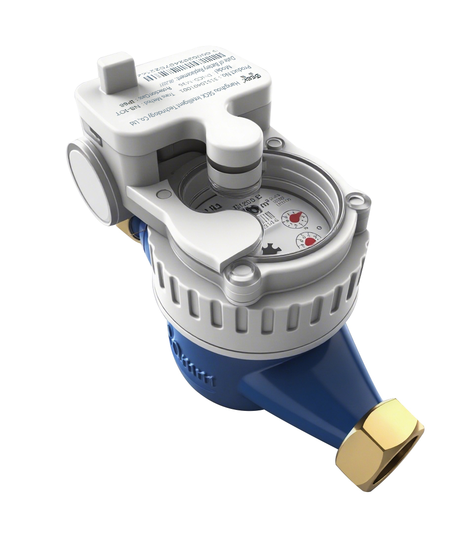
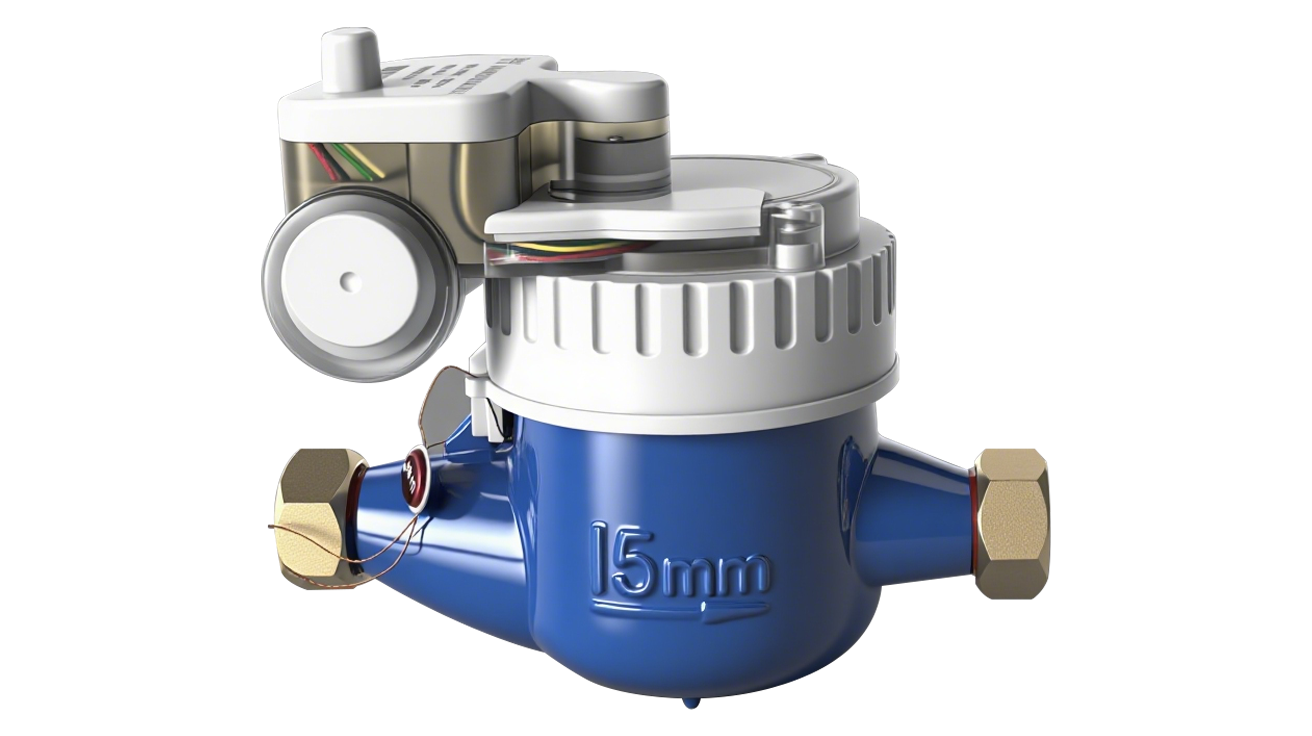
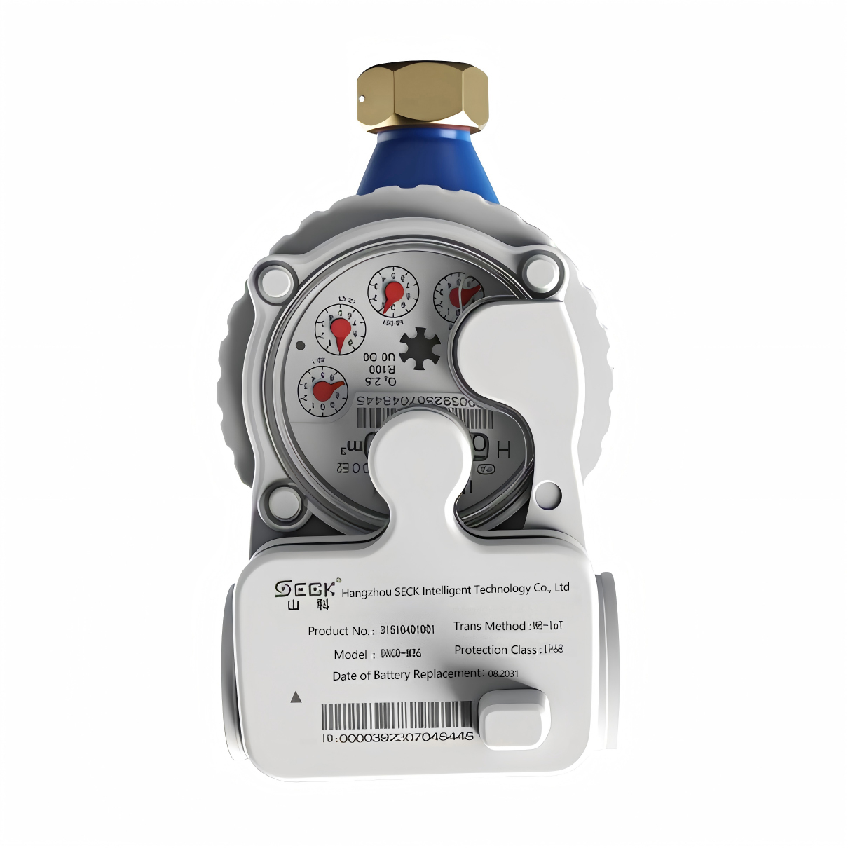
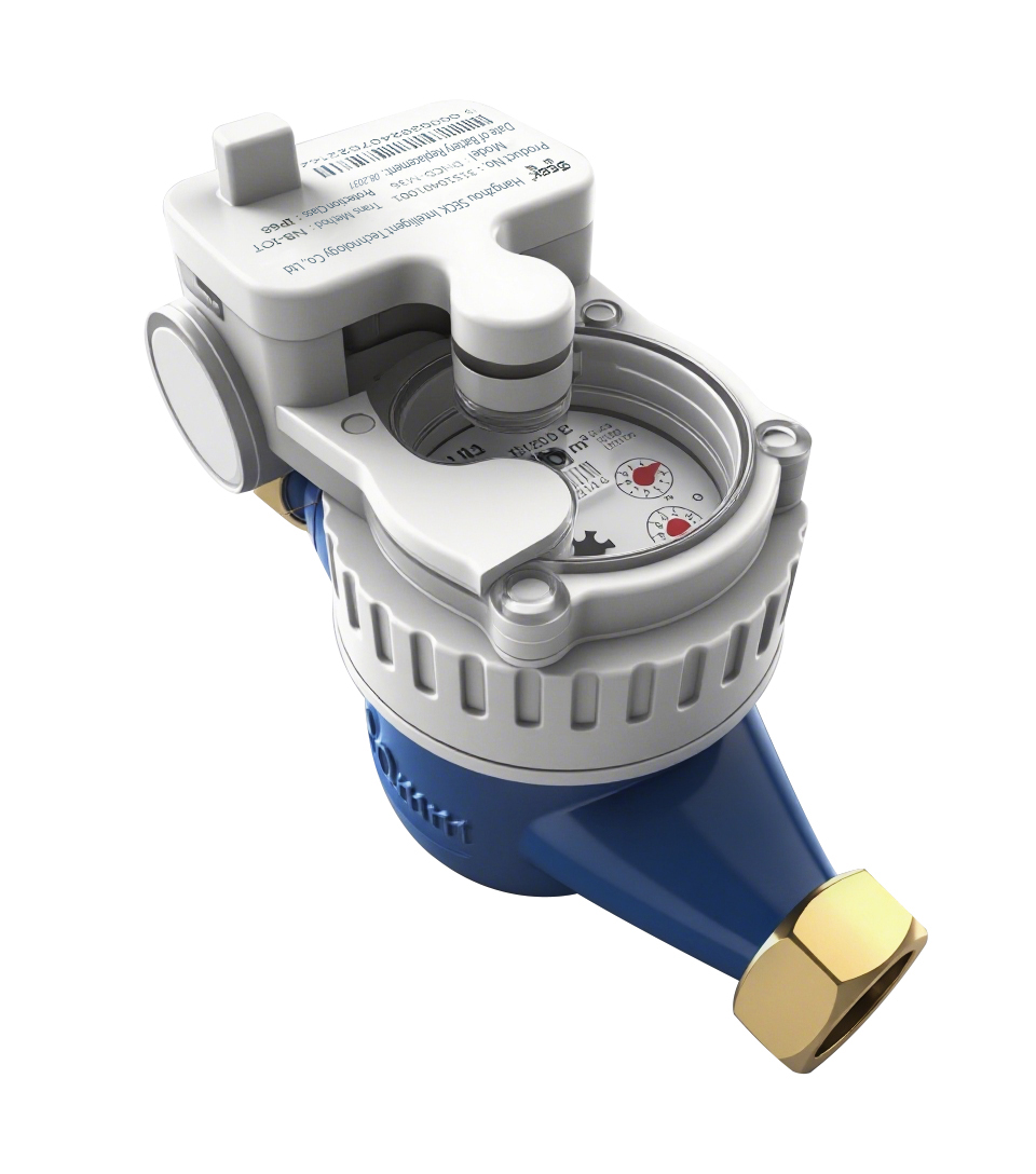


Camera Non-magnetic Smart Water Meter
This product, the SECK Camera Non-magnetic Smart Remote Water Meter, is developed by adding a camera sensor, a non-magnetic sensor, and a smart communication module to a traditional mechanical water meter. It uses camera and non-magnetic data collection principles to gather data and capture images of the water meter's digital display frame simultaneously, eliminating the need for on-site meter verification.
It can communicate via the M-BUS or RS485 bus to enable remote direct reading of water usage.The wireless version of the camera-based direct-reading smart remote water meter, when used with intelligent meter-reading software, enables smart data collection from community water meters and achieves data sharing with the settlement center via networking.
Basic Parameters
Communication Protocol | NB-IOT |
Operating Voltage | 3.6V |
Operating Frequency | Decide based on requirements |
Transmission Range | Within the base station coverage area |
Battery Capacity | 8.5Ah |
Quiescent Current (avg.) | 25μA |
Operating Current (avg.) | 30mA |
Battery Service Life | 7 y |
IP Rating | IP68 |
Pressure Class | MAP10 |
Pressure Loss Class | △p63 |
Temperature Class | T50 |
Flow Profile Sensitivity Class | U10/D5 |
Environmental Safety Class | B/O(Subject to the meter dial indication) |
EMC Class | E1/E2(Subject to the meter dial indication) |
Accuracy Class | 2 |
Flow Parameters
Nominal Diameter (DN) | Range Ratio Q3/Q1 | Overload Flow Rate Q4 | Permanent Flow Rate Q3 | Transitional Flow Rate Q2 | Minimum Flow Rate Q1 | Minimum Reading Min | Maximum Reading Max |
(mm) | (m3/h) | (L/h) | m3 | ||||
15 | 80 | 3.125 | 2.5 | 50 | 31.25 | 0.00005 | 99999 |
100 | 40 | 25 | |||||
125 | 32 | 20 | |||||
160 | 25 | 15.625 | |||||
20 | 80 | 5 | 4 | 80 | 50 | ||
100 | 64 | 40 | |||||
125 | 51.2 | 32 | |||||
160 | 40 | 25 | |||||
25 | 80 | 7.875 | 6.3 | 126 | 78.75 | ||
100 | 100.8 | 63 | |||||
125 | 80.64 | 50.4 | |||||
160 | 63 | 39.375 | |||||
Note:
Refer to the actual values indicated on the register face.
Maximum Permissible Errors:
Low flow zone (from and including minimum flow (Q1) to excluding transitional flow (Q2)): ±5%
High flow zone (from and including transitional flow (Q2) to and including overload flow (Q4)): ±2%
Flow ratios: Q4/Q3= 1.25; Q2/Q1= 1.6
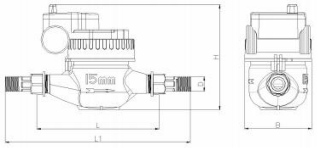
Type | Diameter | L1 | L | B | H | Connection Thread | Connection Thread | Weight |
mm | d | D | kg | |||||
LXSY-15W | 15 | 258 | 165 | 95 | 148 | R1/2 | G3/4 | 1.8 |
LXSY-20W | 20 | 298 | 190 | 95 | 150 | R3/4 | G1 | 2.1 |
LXSY-25W | 25 | 345 | 260 | 95 | 152 | R1 | G1 1/2 | 2.6 |
Note: Dimensions and weight are for reference only; actual product specifications shall prevail. | ||||||||
