Hangzhou SECK Intelligent Technology Co.,Ltd Hangzhou SECK Intelligent Technology Co.,Ltd
CH

Current location :Home > Production Center > Volumetric Mechanical Water Meter

Volumetric Mechanical Water Meter

Volumetric Mechanical Water Meter

▲Compact, lightweight, easy to install, and cost - effective in maintenance.
▲Suitable for cold water from 0 to 30°C.
▲It has high measurement accuracy and meets all the technical requirements of the national standard GB/T778.1~5-2018.
▲High rangeability, meeting Class C standard (R=160 or R=315)

Details

Function Parameters Dimensions

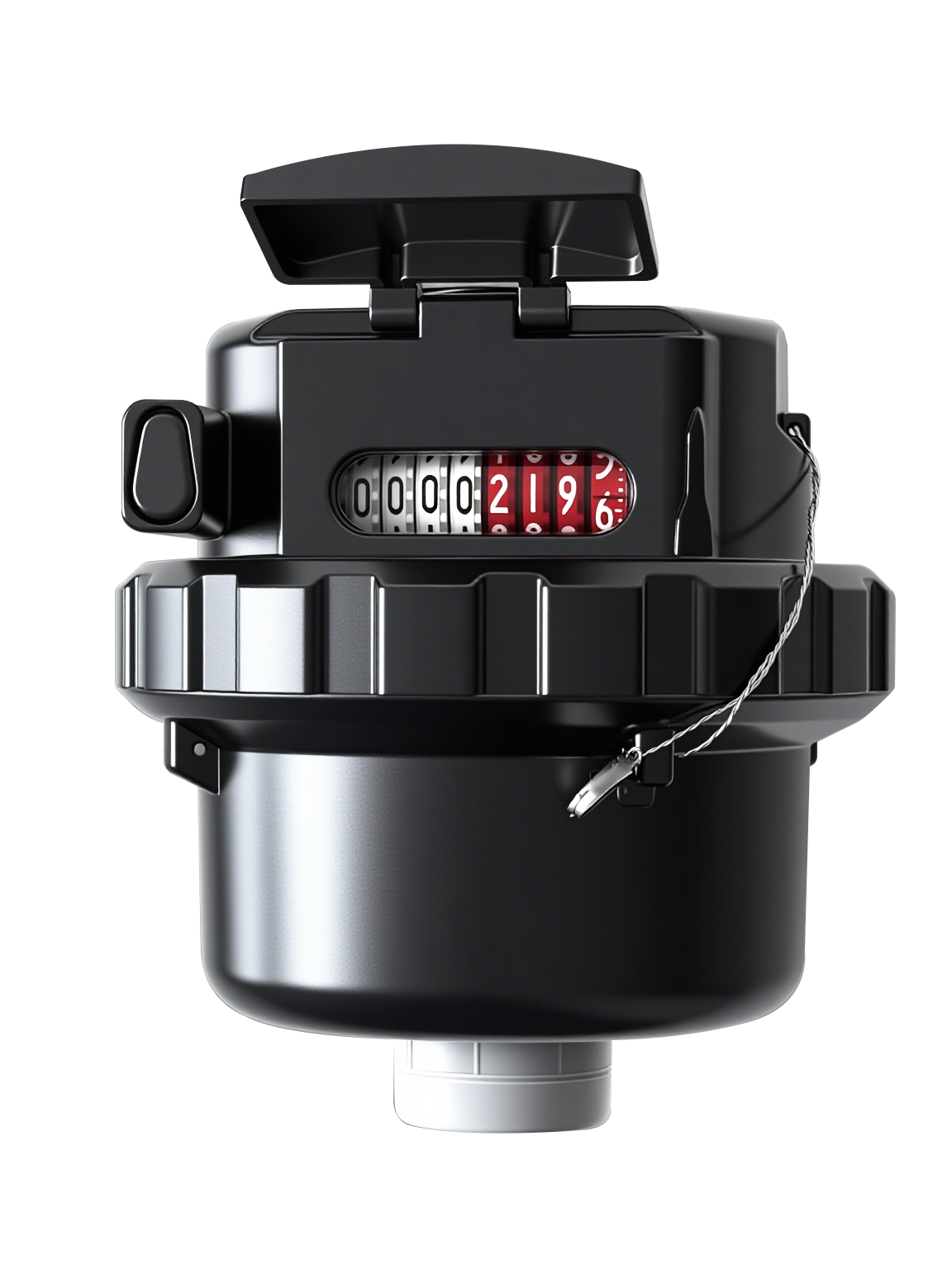
The Volumetric water meter is a device installed in closed pipelines. It comprises chambers of known volume and a mechanical mechanism driven by water flow, where these chambers successively fill with water and then empty. Measured water enters the meter's inlet, and its pressure rotates the piston. Each full rotation cycle of the piston discharges a fixed volume of water from the meter body. Rotation counts are accumulated via a gear reducer, and the total water volume is registered on the counter.


This Volumetric water meter is suitable for small-scale industrial and domestic water applications. It features high measurement accuracy, low minimum starting flow, excellent dirt resistance, convenient reading, an aesthetically pleasing design, hygienic safety, and extended service life. As a positive displacement instrument, the Volumetric water meter delivers reliable long-term performance.


Basic Parameters


Function

Parameter

Measurement Accuracy

2

Operating Temperature

Cold water meter: 0.1℃30℃

Allowable Water Pressure

0.03 MPa1MPa

Pressure Loss Class

△p63

Flow Profile Sensitivity Class

U0D0

Protection Class

IP68

Installation Method

Horizontally or Vertically.


Flow Parameters


Nominal Diameter

Q3/Q1

Overload Flow Rate

Q4

Permanent Flow Rate

Q3

Transitional Flow Rate

Q2

Minimum Flow Rate

Q1

(mm)

m³/h

L/h

15

160

3.125

2.5

25

15.625

20

5

4

40

25

25

7.875

6.3

63

39.375

32

12.5

10

100

62.5

40

20

16

160

100


Note:

Actual values shall prevail as marked on the dial.

Maximum Permissible Errors:

In the low flow zone from and including the minimum flow (Q₁) to excluding the transitional flow (Q₂): ±5%

In the high flow zone from and including the transitional flow (Q₂) to and including the overload flow (Q₄): ±2%


Diameter

H(mm)

W(mm)

Connection Thread  

D

Connection Thread

d

15

115

90

G3/4

R1/2

20

130

96

G3/4

R3/4

25

170

112

G1 1/4

R1 1/4

32

260

139

G1 1/2

R1 1/2

40

300

174

G2

R2

图片